This guide offers a concise exploration of DBC files, key in Controller Area Network (CAN) systems. It covers the essentials of DBC files, which define and interpret CAN bus data, catering to both beginners and advanced users. Gain insights into the structure and application of DBC files for effective communication in CAN networks.
What is a DBC File?
Simply put, a DBC file, or DataBase Container file, is a proprietary format supported by Vector Informatik GmbH. This format serves a crucial role in the field of automotive communication. Just as a decoder ring displays hidden messages, a DBC file sheds light on the complexity of the CAN (Controller Area Network) bus database.
When we talk about raw data from a CAN bus, we're referring to myriad streams of 0s and 1s — binary code that, at first glance, seems indecipherable to the human eye. Yet, this data is loaded with valuable details, from vehicle speed and engine RPMs to sensor status and fault codes. Without a dedicated tool or framework, it can be difficult to draw meaning from this binary sea.
Keep reading, if you want to know how to import DBC files.

Enter the DBC file. As a software application, it maps out the connection between specific binary sequences and their real-world counterparts. It clarifies the bit position, byte order, and value scaling, translating abstract data into physical values that engineers, technicians, and even end-users can understand.
This tool offers the key to uncover the wealth of data stored within each CAN frame, enabling professionals and enthusiasts to diagnose problems, optimize performance, or simply gain insights into their vehicle's inner workings.
In essence, DBC files stand at the intersection of raw data and actionable knowledge, making them indispensable in modern vehicular communication and diagnostics.
The DBC Structure
When you dive into a DBC file, you'll encounter a few key components:
-
DBC message: This includes a Message ID, paired with at least one signal. For instance, an 8-bit signal might represent a single message.
BO_ 500 IO_DEBUG: 4 IO SG_ IO_DEBUG_test_unsigned : 0|8@1+ (1,0) [0|0] "" DBG -
Signed signals: You can introduce these by giving a signal a negative offset. This can be useful in certain data interpretations.
By providing a negative offset to a transmission, a signed signal may be delivered:
BO_ 500 IO_DEBUG: 4 IO SG_ IO_DEBUG_test_unsigned : 0|8@1+ (1,0) [0|0] "" DBG SG_ IO_DEBUG_test_signed : 8|8@1- (1,-128) [0|0] "" DBG -
Fractional signals: These are used to transmit a signal with specific range and precision details.
A fractional signal can be transmitted by specifying the range and, if necessary, the accuracy:
BO_ 500 IO_DEBUG: 4 IO SG_ IO_DEBUG_test_unsigned : 0|8@1+ (1,0) [0|0] "" DBG SG_ IO_DEBUG_test_signed : 8|8@1- (1,-128) [0|0] "" DBG SG_ IO_DEBUG_test_float1 : 16|8@1+ (0.1,0) [0|0] "" DBG SG_ IO_DEBUG_test_float2 : 24|12@1+ (0.01,-20.48) [-20.48|20.47] "" DBG -
Enumeration types: Think of these as signal name tags; instead of a generic number, they give you a readable name.
When the user prefers to view names rather than numbers, an enumeration type is utilized:
BO_ 500 IO_DEBUG: 4 IO SG_ IO_DEBUG_test_enum : 8|8@1+ (1,0) [0|0] "" DBG BA_ "FieldType" SG_ 500 IO_DEBUG_test_enum "IO_DEBUG_test_enum"; VAL_ 500 IO_DEBUG_test_enum 2 "IO_DEBUG_test2_enum_two" 1 "IO_DEBUG_test2_enum_one" ; -
Multiplexed Message: It's like a data-packed suitcase. With a single message ID, these messages can carry more than 8 bytes of data. Depending on the delivered multiplexed value, they can be decoded in various ways.
To transmit a multiplexed message, you must send two different messages, one for the m0 and one for the m1:
BO_ 200 SENSOR_SONARS: 8 SENSOR
                            SG_ SENSOR_SONARS_mux M : 0|4@1+ (1,0) [0|0] "" DRIVER,IO
                            SG_ SENSOR_SONARS_err_count : 4|12@1+ (1,0) [0|0] "" DRIVER,IO
                            SG_ SENSOR_SONARS_left m0 : 16|12@1+ (0.1,0) [0|0] "" DRIVER,IO
                            SG_ SENSOR_SONARS_middle m0 : 28|12@1+ (0.1,0) [0|0] "" DRIVER,IO
                            SG_ SENSOR_SONARS_right m0 : 40|12@1+ (0.1,0) [0|0] "" DRIVER,IO
                            SG_ SENSOR_SONARS_rear m0 : 52|12@1+ (0.1,0) [0|0] "" DRIVER,IO
                            SG_ SENSOR_SONARS_no_filt_left m1 : 16|12@1+ (0.1,0) [0|0] "" DBG
                            SG_ SENSOR_SONARS_no_filt_middle m1 : 28|12@1+ (0.1,0) [0|0] "" DBG
                            SG_ SENSOR_SONARS_no_filt_right m1 : 40|12@1+ (0.1,0) [0|0] "" DBG
                            SG_ SENSOR_SONARS_no_filt_rear m1 : 52|12@1+ (0.1,0) [0|0] "" DBG
Here's a DBC file example:
VERSION ""


                        NS_ :
                        BA_
                        BA_DEF_
                        BA_DEF_DEF_
                        BA_DEF_DEF_REL_
                        BA_DEF_REL_
                        BA_DEF_SGTYPE_
                        BA_REL_
                        BA_SGTYPE_
                        BO_TX_BU_
                        BU_BO_REL_
                        BU_EV_REL_
                        BU_SG_REL_
                        CAT_
                        CAT_DEF_
                        CM_
                        ENVVAR_DATA_
                        EV_DATA_
                        FILTER
                        NS_DESC_
                        SGTYPE_
                        SGTYPE_VAL_
                        SG_MUL_VAL_
                        SIGTYPE_VALTYPE_
                        SIG_GROUP_
                        SIG_TYPE_REF_
                        SIG_VALTYPE_
                        VAL_
                        VAL_TABLE_


                        BS_:


                        BU_: DBG DRIVER IO MOTOR SENSOR


                        BO_ 100 DRIVER_HEARTBEAT: 1 DRIVER
                        SG_ DRIVER_HEARTBEAT_cmd : 0|8@1+ (1,0) [0|0] "" SENSOR,MOTOR


                        BO_ 500 IO_DEBUG: 4 IO
                        SG_ IO_DEBUG_test_unsigned : 0|8@1+ (1,0) [0|0] "" DBG
                        SG_ IO_DEBUG_test_enum : 8|8@1+ (1,0) [0|0] "" DBG
                        SG_ IO_DEBUG_test_signed : 16|8@1- (1,0) [0|0] "" DBG
                        SG_ IO_DEBUG_test_float : 24|8@1+ (0.5,0) [0|0] "" DBG


                        BO_ 101 MOTOR_CMD: 1 DRIVER
                        SG_ MOTOR_CMD_steer : 0|4@1- (1,-5) [-5|5] "" MOTOR
                        SG_ MOTOR_CMD_drive : 4|4@1+ (1,0) [0|9] "" MOTOR


                        BO_ 400 MOTOR_STATUS: 3 MOTOR
                        SG_ MOTOR_STATUS_wheel_error : 0|1@1+ (1,0) [0|0] "" DRIVER,IO
                        SG_ MOTOR_STATUS_speed_kph : 8|16@1+ (0.001,0) [0|0] "kph" DRIVER,IO


                        BO_ 200 SENSOR_SONARS: 8 SENSOR
                        SG_ SENSOR_SONARS_mux M : 0|4@1+ (1,0) [0|0] "" DRIVER,IO
                        SG_ SENSOR_SONARS_err_count : 4|12@1+ (1,0) [0|0] "" DRIVER,IO
                        SG_ SENSOR_SONARS_left m0 : 16|12@1+ (0.1,0) [0|0] "" DRIVER,IO
                        SG_ SENSOR_SONARS_middle m0 : 28|12@1+ (0.1,0) [0|0] "" DRIVER,IO
                        SG_ SENSOR_SONARS_right m0 : 40|12@1+ (0.1,0) [0|0] "" DRIVER,IO
                        SG_ SENSOR_SONARS_rear m0 : 52|12@1+ (0.1,0) [0|0] "" DRIVER,IO
                        SG_ SENSOR_SONARS_no_filt_left m1 : 16|12@1+ (0.1,0) [0|0] "" DBG
                        SG_ SENSOR_SONARS_no_filt_middle m1 : 28|12@1+ (0.1,0) [0|0] "" DBG
                        SG_ SENSOR_SONARS_no_filt_right m1 : 40|12@1+ (0.1,0) [0|0] "" DBG
                        SG_ SENSOR_SONARS_no_filt_rear m1 : 52|12@1+ (0.1,0) [0|0] "" DBG


                        CM_ BU_ DRIVER "The driver controller driving the car";
                        CM_ BU_ MOTOR "The motor controller of the car";
                        CM_ BU_ SENSOR "The sensor controller of the car";
                        CM_ BO_ 100 "Sync message used to synchronize the controllers";


                        BA_DEF_ "BusType" STRING ;
                        BA_DEF_ BO_ "GenMsgCycleTime" INT 0 0;
                        BA_DEF_ SG_ "FieldType" STRING ;


                        BA_DEF_DEF_ "BusType" "CAN";
                        BA_DEF_DEF_ "FieldType" "";
                        BA_DEF_DEF_ "GenMsgCycleTime" 0;


                        BA_ "GenMsgCycleTime" BO_ 100 1000;
                        BA_ "GenMsgCycleTime" BO_ 500 100;
                        BA_ "GenMsgCycleTime" BO_ 101 100;
                        BA_ "GenMsgCycleTime" BO_ 400 100;
                        BA_ "GenMsgCycleTime" BO_ 200 100;
                        BA_ "FieldType" SG_ 100 DRIVER_HEARTBEAT_cmd "DRIVER_HEARTBEAT_cmd";
                        BA_ "FieldType" SG_ 500 IO_DEBUG_test_enum "IO_DEBUG_test_enum";


                        VAL_ 100 DRIVER_HEARTBEAT_cmd 2 "DRIVER_HEARTBEAT_cmd_REBOOT" 1 "DRIVER_HEARTBEAT_cmd_SYNC" 0
                        "DRIVER_HEARTBEAT_cmd_NOOP" ;
                        VAL_ 500 IO_DEBUG_test_enum 2 "IO_DEBUG_test2_enum_two" 1 "IO_DEBUG_test2_enum_one" ;
The Description Field in DBC Files
When it comes to DBC files, most people focus on the essentials like signal names and attributes. However, the often-overlooked 'Description Field' serves as a hidden gem for elevating your data analysis. This field isn't just a placeholder; it's an opportunity for nuanced communication and clarity.
The Description Field allows you to explain each signal with specific details, from its role in the system to the expected range of values. In essence, it's your metadata playground — a space to convey vital information that the raw signal data can't capture alone. This not only enriches the dataset but also empowers engineers and data scientists to work more effectively, reducing guesswork and enabling precise calibration.
A segment of a DBC file with a description field might look like this:
VERSION "1.0"

                        NS_:
                          NS_DESC_
                          NS_SIG_
                          NS_VAL_

                        BS_:

                        BU_: ECU1 ECU2

                        BO_ 1 Message_1: 8 ECU1
                         SG_ Signal_1 : 0|8@1+ (1,0) [0|255] "" ECU2
                         SG_ Signal_2 : 8|8@1+ (1,0) [0|255] "" ECU2

                         CM_ SG_ 1 Signal_1 "This signal is used for temperature reading in Fahrenheit."
                         CM_ SG_ 1 Signal_2 "This signal represents the fuel level as a percentage."

                        VAL_ 1 Signal_1 0 "Low" 255 "High";
                        VAL_ 1 Signal_2 0 "Empty" 100 "Full";
Why DBCs Matter: Real-Life Applications
DBC files play an indispensable role in the modern tech landscape, especially within the automotive and industrial sectors. Here are some concise highlights of their real-world applications:
Vehicle Diagnostics: OEM (Original Equipment Manufacturer) mechanics utilize DBC files for accurate CAN data logging, making diagnostics quicker and more precise.
Fleet Management and J1939 DBC: DBCs, particularly the J1939 standard, are crucial in managing heavy-duty vehicle fleets. They extract valuable insights from the CAN bus system, aiding in efficient fleet operations.
Performance Tuning with OBD2 Data: Car enthusiasts and professionals use DBCs to decode complex OBD2 data for performance tweaks, ensuring optimal and safe vehicle performance.
Predictive Maintenance: DBC files transform raw CAN data into insights, which can be used for timely maintenance interventions, preventing costly breakdowns.
Safety and Advanced Driver Assistance Systems (ADAS): Vehicles’ safety systems rely on sensors, with DBCs ensuring data is interpreted accurately for seamless functionality.
Beyond Automotive – Agriculture and Industrial Automation: DBCs aren’t limited to vehicles. They're vital in agriculture machinery and industrial automation, ensuring error-free communication.
In essence, DBC files are the cornerstone in transforming complex electronic data into actionable insights across various sectors.
DBC File Guide Video
Step-by-Step Guide to Importing DBC Files
Now, let's look at how to import DBC files! If you're eager to try out these steps in a hands-on manner, don't hesitate to schedule to get free access to our demo environment. This interactive platform allows you to follow along with the guide and experience the ease of managing DBC files firsthand. Let's dive into the steps:
-
Initiating the Process: Begin by registering on the AutoPi demo environment. This is your first step into a world of efficient fleet management.

-
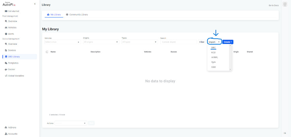
Navigating to the OBD Library: Once you're logged in, you'll find yourself at the fleet management overview. Look to the left sidebar under "Device Management" and locate the "OBD Library". Click here to proceed.

-
Importing a File: In the OBD Library, you'll notice an "Import" button. Clicking this prepares you for the file import process.

-
Selecting Import File: A pop-up window will emerge, guiding you to the next step. Here, choose the option to 'Import File.'

-
Choosing Your DBC File: At this juncture, you're ready to select the DBC file you wish to import. Browse your computer to find and select the desired file.

-
Uploading the File: After selecting your file, ensure it's fully loaded and then hit the 'Upload' button. This step integrates your file into the system.

-
Finalizing the Import: Congratulations, your DBC file is now successfully imported to the AutoPi Cloud! You can now view all your files and have the option to edit the CAN message DBC file as needed.


For those looking for more in-depth knowledge and tips on managing DBC files, we've got you covered. Follow this link for a more comprehensive exploration of the subject. Your journey into effective fleet management and DBC file handling starts here!
Concluding Thoughts
In the world of CAN data, DBC files function as the translator, bridging the gap between raw data and actionable insights.
Whether you're a software expert or someone dabbling in the world of data and sensors, understanding the importance and application of DBC files is a game-changer. With tools like AutoPi Cloud and software programs tailored for DBC file interpretation, the future of CAN data analysis seems both exciting and promising.


