Welcome to our comprehensive guide on the J1939 protocol!
In this blog post, we'll break down the complexities of the J1939 protocol into simple, digestible pieces. Our goal is to make sure you walk away with a clear understanding of what J1939 is, why it's important, and how it works.
The J1939 protocol is a cornerstone of modern vehicle communication networks, especially in the commercial vehicle industry. It plays a critical role in everything from diagnostics to telematics, making it essential knowledge for anyone working with or interested in automotive technology.
By the end of this guide, you'll have a solid grasp of the basics and be well-equipped to dive deeper into more advanced topics.
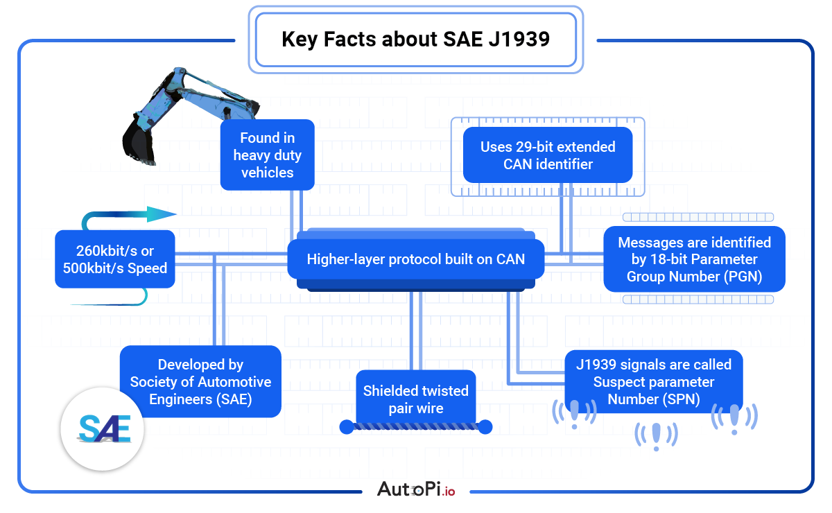
Quick Key Facts about SAE J1939
-
Found in heavy-duty vehicles
-
Uses a 29-bit extended CAN identifier
-
Developed by SAE
-
Speed is typically 250 kbit/s or 500 kbit/s
-
Higher-layer protocol built on CAN
-
Utilizes shielded twisted pair wire
-
Messages are identified by an 18-bit parameter group number
-
J1939 signals are referred to as suspect parameter numbers
What is J1939?
To understand the J1939 protocol, let's start with the basics.
The J1939 protocol is a set of standards defined by the Society of Automotive Engineers (SAE) for communication and diagnostics among vehicle components. It is primarily used in heavy-duty vehicles like trucks, buses, and construction equipment.
Now, let's break down the J1939 protocol to understand its fundamental components.
-
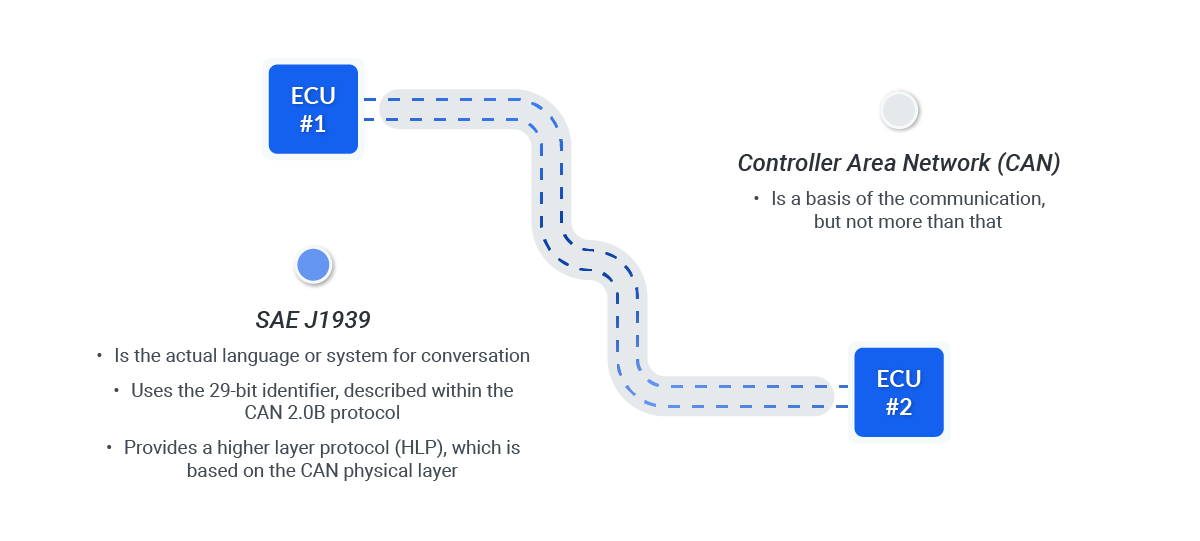
Network Communication: Think of J1939 as a common language that different parts of a vehicle use to talk to each other.
Just like how people need a common language to communicate effectively, vehicle components need the J1939 protocol to exchange information seamlessly.
-
Controller Area Network (CAN) The J1939 protocol operates over a CAN bus, a robust vehicle bus standard designed to allow microcontrollers and devices to communicate with each other without a host computer.
It’s like the nervous system of the vehicle, transmitting data quickly and reliably.
-
Parameters and Messages: In J1939, data is transmitted in the form of messages, each containing specific information about vehicle performance, status, and diagnostics.
These messages use predefined parameters and data formats to ensure consistency and accuracy.
The J1939 protocol is essential because it standardizes communication in heavy-duty vehicles, making it easier for manufacturers to design compatible components and systems. This standardization leads to improved efficiency, reliability, and safety in vehicle operations.
The J1939 protocol was developed in the 1990s by the SAE to address the growing complexity of vehicle electronics. Before J1939, different manufacturers used their proprietary communication methods, making interoperability a significant challenge. J1939 provided a unified solution, revolutionizing how heavy-duty vehicles communicate internally.
According to industry experts, J1939's standardized approach has been crucial in advancing vehicle telematics and diagnostics. It has allowed for more sophisticated data collection and analysis, leading to better vehicle maintenance and performance optimization.
For more information, check out the SAE J1939 Standards Collection.
Why is J1939 Important?
Understanding the importance of the J1939 protocol helps us appreciate its role in the automotive industry, especially in heavy-duty vehicles.
Here, we'll explore its applications and benefits to give you a clearer picture of why J1939 is essential.
-
Telematics: J1939 is widely used in vehicle telematics systems, which gather and transmit data on vehicle usage, maintenance needs, and performance. This data helps fleet managers monitor and optimize their operations, leading to cost savings and improved efficiency.
-
Diagnostics: J1939 plays a crucial role in vehicle diagnostics by providing standardized codes and messages that technicians use to identify and fix issues. This standardization simplifies the diagnostic process, making it faster and more accurate.
-
Engine Control: Many modern engines use the J1939 protocol to communicate between different control units, ensuring smooth and efficient operation. For instance, it helps coordinate the fuel injection system, transmission, and other critical components.
And here are some of the key benefits of J1939:
-
Interoperability: One of the main advantages of J1939 is that it allows components from different manufacturers to work together seamlessly. This interoperability simplifies the design and integration of vehicle systems, reducing costs and development time.
-
Reliability: J1939’s use of the CAN bus standard ensures reliable and robust communication even in harsh vehicle environments. This reliability is crucial for maintaining vehicle performance and safety.
-
Scalability: The J1939 protocol is highly scalable, making it suitable for a wide range of vehicles, from small trucks to large construction equipment. Its flexibility allows it to adapt to various applications and requirements.
-
Standardization: With standardized communication, vehicle manufacturers can streamline production and maintenance processes. This standardization reduces the learning curve for technicians and engineers, leading to faster issue resolution and more efficient vehicle management.
-
Data Richness: J1939 provides detailed data on vehicle performance and status, which can be used for advanced analytics. This data richness enables proactive maintenance, predictive diagnostics, and more informed decision-making for fleet management.
J1939 has been a key part of our vehicle
telematics toolkit for years,
says Malte, CPO at AutoPi. It's
dependable and makes vehicle diagnostics and telematics so much easier. Our clients see real benefits, like less
downtime and better performance, which makes a big difference in their day-to-day operations.

Make Fleet Management Easier with AutoPi CAN FD Pro
Alright, so now that you have got a solid grasp of J1939, let me tell you about something that could make life a lot easier if you are managing a fleet of heavy machinery or trucks—the AutoPi CAN FD Pro.
If you are like me, you probably want things to run as smoothly as possible without a bunch of headaches. This device logs data from dual CAN and CAN-FD buses, and guess what? If you have got more buses you need to track, you can connect them up through external interfaces. It’s pretty flexible like that.
Now, here’s the cool part—everything gets uploaded to the cloud continuously. You can send raw or decoded data to places like AWS S3, so your team can pull it from anywhere. There is no more scrambling for info when you need it. Plus, the device has 32GB of internal storage—and you can hook up external USB drives to get more space if you need it. No worries about running out of room!
But the best thing? This tool can help you with real-time diagnostics and predictive maintenance. If your equipment is starting to show signs of something going wrong, you’ll know before it breaks down. With the AutoPi CAN FD Pro, it’s like having a backup mechanic on hand 24/7, helping you keep everything running smoothly.
Basic Components of J1939
Before we get into how the J1939 protocol works, it's important to know its basic components. Let’s break it down into its essential parts and see how they all fit together.
Network Architecture
As mentioned, the J1939 protocol operates over a Controller Area Network (CAN) bus, which is like the central nervous system of a vehicle. It allows different components of the vehicle to communicate with each other efficiently.
Think of it as a network of interconnected nodes, where each node represents a vehicle component like the engine, transmission, or brakes. These nodes send and receive data, ensuring everything works harmoniously.
J1939 Pinout
The J1939 pinout refers to how the wires and connectors in the CAN bus system are arranged. Getting the pinout right is essential for setting up and troubleshooting your J1939 networks.
Below is a detailed pin layout for a standard 9-pin J1939 connector, which you'll find in both black and green stick types.
9-Pin Layout:
-
A | Ground: This pin provides the ground connection, completing the electrical circuit.
-
B | +12V: This pin supplies 12 volts of power to the system, essential for powering the network.
-
C | CAN 1 / J1939 High: This pin carries the high side of the first CAN or J1939 network, critical for data communication.
-
D | CAN 1 / J1939 Low: This pin carries the low side of the first CAN or J1939 network, working together with CAN high for proper data transmission.
-
E | CAN 1 / J1939 Shield: This pin is connected to a shielded cable to reduce electromagnetic interference and protect the integrity of the CAN 1 / J1939 signals.
-
F | J1708 / 1587 / CAN 2 High: This pin carries the high side of the second network, which could be either J1708, J1587, or a second CAN network, depending on the application.
-
G | J1708 / 1587 / CAN 2 Low: This pin carries the low side of the second network, paired with CAN 2 High for data transmission.
-
H | OEM Specific: This pin is reserved for Original Equipment Manufacturer (OEM) specific functions, which could vary depending on the manufacturer
-
J | OEM Specific: Another pin reserved for OEM-specific functions, providing flexibility for manufacturer-defined uses.
Main difference between black and green stick types:
-
Black Stick Type: Generally used in diagnostic applications. It includes all 9 pins but often lacks the internal termination resistor, meaning it may need an external resistor to function properly in some setups.
-
Green Stick Type: Typically used in production vehicles and includes an internal 120-ohm termination resistor between the CAN High and CAN Low lines. This helps to prevent signal reflections, making it a more self-contained option for many applications.

Each pin plays a crucial role in ensuring your J1939 network runs smoothly and reliably. Whether you’re using a black or green stick type, these pins must be connected properly to avoid communication errors or network failures.
Data Messages
In J1939, data is communicated through messages. Each message contains specific information about vehicle performance, status, and diagnostics. These messages are made up of several fields:
-
Parameter Group Numbers (PGNs): These are unique identifiers that define the type of data being transmitted. Each PGN corresponds to a specific set of parameters related to vehicle performance or status.
-
Suspect Parameter Numbers (SPNs): These are specific data points within a PGN. For example, an SPN might represent the engine speed, fuel level, or oil pressure.
-
Data Length Code (DLC): This indicates the size of the data in the message. It ensures that the receiving node knows how much data to expect.
-
Priority: Since multiple messages can be sent over the network simultaneously, each message has a priority level. High-priority messages get transmitted first to ensure critical information is delivered promptly.
J1939 PGNs & J1939 SPNs
In order to understand how J1939 works, we need to dive a little deeper into PGNs and SPNs. A PGN acts like a container holding several SPNs, which are the actual data points.
For instance, a PGN related to the engine might include SPNs for engine speed, coolant temperature, and oil pressure. This structure ensures that data is organized and easy to interpret.
How the components works together
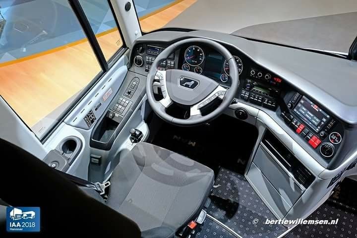
To help visualize how these components work together, imagine a vehicle's dashboard.
The dashboard displays various indicators like speed, fuel level, and warning lights. Behind the scenes, the J1939 protocol is busy transmitting data between different vehicle components to update these indicators in real-time.
Here’s a simple analogy: Think of the CAN bus as a highway, PGNs as different types of vehicles (trucks, cars, motorcycles), and SPNs as the passengers inside those vehicles. The highway (CAN bus) facilitates the movement of these vehicles (PGNs), and each passenger (SPN) carries specific information needed to keep the system running smoothly.
By understanding these basic components, you can see how the J1939 protocol ensures seamless communication within a vehicle, making it an essential part of modern automotive technology.
How J1939 protocol Works
Understanding how the J1939 protocol works involves looking at the process of data communication within a vehicle. This protocol ensures that all the electronic components within a vehicle can communicate seamlessly, enabling efficient operation and diagnostics.
To make sure we got the details right, I teamed up with Henrik, one of our senior developers at AutoPi. He’s got a wealth of experience working with J1939.
The J1939 protocol is a game-changer. It keeps everything in sync and helps us catch issues before they
become
problems, making vehicle management so much smoother for our clients.
— Henrik, CTO
Here’s a step-by-step breakdown, including the technical aspects:
Step 1: Data Generation
Various sensors and electronic control units (ECUs) in the vehicle continuously monitor parameters such as engine temperature, fuel level, and speed. Each of these parameters is captured as raw data.
For example, the engine control unit might monitor engine RPM and coolant temperature.
Step 2: Data Packaging
The raw data from the sensors is packaged into structured format using PGNs and SPNs. As mentioned, PGNs act like folders that group related data, while SPNs are specific data points within these folders.
-
PGNs: Group related data together (e.g., all data about the engine).
-
SPNs: Identify specific data points within the PGN (e.g., engine speed, oil pressure).
Step 3: Message Creation
A message is created by combining the PGN, SPN, and the actual data values. This message also includes a Data Length Code (DLC) to indicate the size of the data and a priority level.
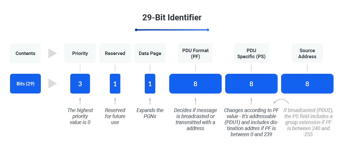
Here i an example of a J1939 message code:
18FEF100 8 00 00 4B 12 00 00 00 00
This code can be broken down into:
-
18FEF100: The identifier which includes the priority, PGN, and source address.
-
18: Priority (higher priority is indicated by a lower value).
-
FEF1: PGN (in hexadecimal).
-
00: Source Address (the address of the transmitting ECU).
-
-
8: DLC (indicating 8 bytes of data).
-
00 00 4B 12 00 00 00 00: The data bytes.
Here's another example:
Step 4: Priority Assignment
Each message is assigned a priority level. Critical messages related to safety or essential operations are given higher priority to ensure they are transmitted first.
For instance, a message about engine overheating would have a higher priority than a message about the cabin temperature.
Step 5: Broadcasting the Message
The message is broadcasted over the CAN bus, which acts like a central highway for data within the vehicle. All ECUs and sensors connected to this highway can access the message.
This broadcasting method ensures that all relevant components receive the necessary information without delay.
Step 6: Message Reception
All connected components listen to the CAN bus and pick up messages relevant to them. For example, the dashboard control unit will listen for messages about speed, fuel level, and warnings. Each component filters out messages that are not relevant to its operation.
Step 7: Data Decoding
Upon receiving the message, the component decodes the data using the PGN and SPN to understand the specific parameters. The DLC helps ensure the entire message is correctly interpreted.
This decoding process allows the component to understand what action, if any, needs to be taken based on the received data.
Step 8: Understanding the PGN Message Board
A PGN message board is a table that lists all the PGNs and their corresponding parameters. And here's a simplified example:
|
PGN (Hex)
|
Description
|
SPNs Included
|
|---|---|---|
| F004 | Engine Temperature | SPN 110: Engine Coolant Temperature |
| FECA | Fuel Level | SPN 96: Fuel Level |
| FEF1 | Engine Speed | SPN 190: Engine Speed, SPN 512: Turbo Speed |
This table helps in organizing and understanding the various messages that can be transmitted and received.
Step 9: Action Based on Data
Once decoded, the data triggers appropriate actions.
For instance, if the received message indicates that the engine temperature is too high, the dashboard will display a warning light to alert the driver.
This real-time communication ensures that the driver can take immediate action to prevent any potential issues.
Example Scenario
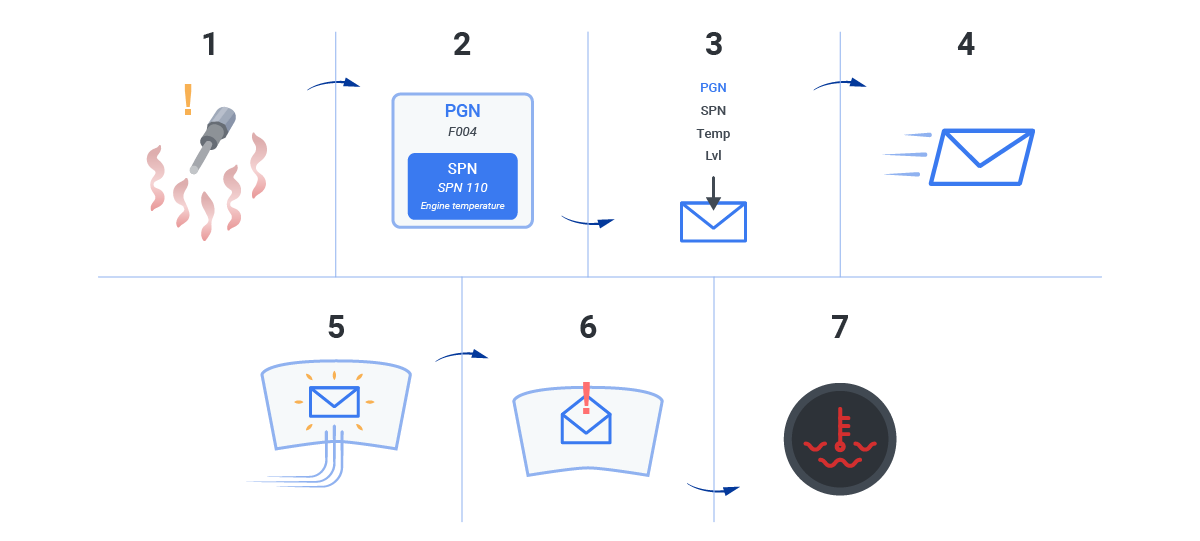
Imagine you're driving a truck, and the engine temperature sensor detects that the engine is overheating. Here’s how the J1939 protocol would handle this:
-
Data Generation: The temperature sensor records a high temperature reading.
-
Data Packaging: The sensor packages this data with a PGN for engine status (e.g., F004) and an SPN for engine temperature (e.g., SPN 110).
-
Message Creation: A message is created with the PGN, SPN, temperature value, and a high priority level.
-
Broadcasting: The message is sent out over the CAN bus.
-
Reception: The dashboard control unit, listening to the CAN bus, receives the message.
-
Decoding: The dashboard decodes the message, understanding it indicates a high engine temperature.
-
Action: The dashboard lights up a warning indicator to alert you of the overheating engine.
By following these steps, the J1939 protocol ensures that all parts of the vehicle communicate effectively, keeping everything running smoothly and safely.
J1939 Common Use Cases
The J1939 protocol is widely used across various applications in the automotive industry, particularly in heavy-duty vehicle management. Here are some of the key areas where J1939 is indispensable:
Telematics
One of the primary uses of J1939 is in vehicle telematics systems. Telematics involves the collection and transmission of data from the vehicle to remote systems. This data includes information about vehicle location, speed, fuel consumption, and maintenance needs.
-
Fleet Management: Fleet managers use telematics to monitor the health and performance of their vehicles in real time. This helps them make informed decisions about maintenance schedules, route planning, and overall fleet efficiency.
For instance, data on fuel consumption and driver behavior can be analyzed to optimize routes and reduce costs.
Diagnostics
J1939 is also essential for vehicle diagnostics. When a vehicle component detects an issue, it sends a diagnostic message over the CAN bus using the J1939 protocol. This message contains diagnostic trouble codes (DTCs) that pinpoint the problem.
-
Maintenance: Mechanics use these diagnostic messages to quickly identify and resolve issues. Instead of spending hours troubleshooting, they can immediately see which component is malfunctioning and take corrective action. This leads to faster repairs and less downtime for the vehicle.
Engine Control
Modern engines rely heavily on the J1939 protocol for internal communication. Different parts of the engine, such as the fuel injection system, turbocharger, and exhaust system, must work together harmoniously.
-
Performance Optimization: J1939 enables these components to communicate efficiently, ensuring that the engine runs smoothly and efficiently.
For example, data on engine speed and load can be used to adjust fuel injection timing for optimal performance.
Example Scenario
One of our clients runs a busy mining site and relies on several heavy machines, including Kubota tractor. They came to us with an interesting challenge: they wanted to understand more about the queries made by their diagnostic tools to keep their machinery in top shape.
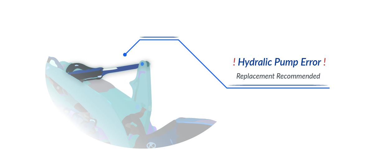
We set up their tractors with our telematics system using the J1939 protocol. This allowed us to track and analyze data from their machines in real time. After a few weeks, we noticed something odd — there were some unusual diagnostic messages showing drops in hydraulic pressure in one of the tractors.
By digging deeper into these messages, we discovered that the hydraulic pump was acting up, something that wasn’t obvious at first. Thanks to the detailed insights, the client was able to replace the pump before it caused any serious problems.
This small fix made a big difference. It prevented what could have been a costly breakdown and kept their operations running smoothly.
This experience showed us once again how powerful J1939 is. It’s always rewarding to see how a bit of technical know-how can make such a big impact.
Challenges and Limitations
While the J1939 protocol is incredibly powerful and versatile, it's not without its challenges and limitations. Understanding these can help you make the most out of the protocol and be prepared to address potential issues.
Technical Challenges
-
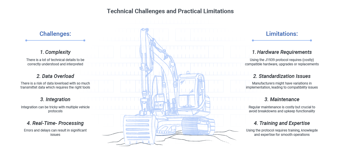
Complexity: The J1939 protocol involves a lot of technical details and specific configurations. For beginners, this can be quite overwhelming. Each message contains multiple elements like PGNs, SPNs, and DLCs that need to be correctly understood and interpreted.
-
Data Overload: With so much data being transmitted continuously, there’s a risk of data overload. Managing and making sense of this vast amount of data requires sophisticated tools and expertise.
-
Integration: Integrating J1939 with other systems and protocols can be tricky. Vehicles often use multiple communication protocols, and ensuring seamless interoperability between these can be a complex task.
-
Real-Time Processing: For applications requiring real-time data processing, any delays or errors in data transmission can lead to significant issues. Ensuring that the system processes and responds to data in real-time requires robust infrastructure.
Practical Limitations
-
Hardware Requirements: Implementing the J1939 protocol requires compatible hardware, which can be costly. Ensuring that all components of the vehicle can communicate using J1939 might involve significant upgrades or replacements.
-
Standardization Issues: Although J1939 is a standard protocol, different manufacturers might have variations in implementation. This can lead to compatibility issues when integrating components from different suppliers.
-
Maintenance: Keeping the system updated and ensuring that all components are functioning correctly can be challenging. Regular maintenance is crucial to avoid communication breakdowns and ensure the system’s reliability.
-
Training and Expertise: Utilizing the J1939 protocol effectively requires training and expertise. Ensuring that your team is well-versed in the protocol and can troubleshoot issues as they arise is essential for smooth operations.
To give you a better perspective, here’s what Henrik, our CTO at AutoPi, has to say about these challenges:
Working with J1939 is rewarding, but it has its challenges. One of the biggest is making sure it
integrates seamlessly with existing systems. Every vehicle has its quirks, so getting everything to
communicate
smoothly takes careful planning and testing. But when it all comes together, the benefits are clear.
By being aware of these challenges and limitations, you can better prepare for and navigate potential issues when working with the J1939 protocol. This awareness will help you maximize the protocol's benefits while minimizing its drawbacks.
The Future of J1939
We’re always looking ahead to how the J1939 protocol can better serve those working with heavy-duty machinery. Here’s how we see it evolving to meet practical needs right now and in the near future:
-
Imagine being able to predict maintenance needs before they cause downtime. With J1939, you can leverage the vast amounts of data generated by your machinery to foresee issues and perform maintenance proactively, ensuring your operations run smoothly and efficiently.
-
The Internet of Things (IoT) is revolutionizing how we manage machinery. By integrating J1939 with IoT devices, you can gain deeper insights into how your equipment performs and how it’s being used. This means you can optimize operations, improve efficiency, and reduce costs by making data-driven decisions.
-
As machinery becomes more connected, protecting it from cyber threats is critical. Strengthening security measures within J1939 ensures that your communication systems are safe, helping you avoid disruptions and maintain the integrity of your operations.
-
With the rise of electric and autonomous heavy machinery, J1939 is adapting to support these advanced technologies. This means better management of battery systems and advanced operational tech, ensuring your machinery is ready for the future of automation and electrification.
At AutoPi, we’re excited about these advancements because they’re not just about future possibilities—they’re about making your operations more efficient, safe, and sustainable today.
Conclusion
We hope this guide has made the J1939 protocol clearer and highlighted its importance in heavy-duty machinery. Understanding J1939 unlocks your equipment’s full potential, ensuring smooth and efficient operations.
By now, you should have a good grasp of what J1939 is, how it works, and why it matters. From its core components and communication process to practical uses and future trends, J1939 is vital for managing and operating heavy-duty vehicles.
At AutoPi, we're here to help you leverage J1939 to its fullest. Whether you need to enhance fleet management, improve diagnostics, or gear up for future tech, our team is ready to assist.
Additional Resources
For further reading and detailed information, check out these resources:
Thank you for reading. If you have any questions or need further support, don’t hesitate to reach out to us at AutoPi. Our team of experts is here to help you optimize your heavy-duty machinery and drive your operations forward.
Contact us today and let's take your operations to the next level!
If you have any interest in working on your own vehicle or as a mechanic or technician, understanding OBD-II PIDs is essential, with each code giving you detailed insight into your car’s health and performance, so it is easier and faster to maintain and troubleshoot when required.


